
Oxygen sensor circuit diagram
Zener Diode: D1 = 9V1 IzRm 5.6mA
Diodes: D2/D3/D4=1N4001 Diode,Max Pd=2.5W,Max I=1A@75OC, MAX reverse voltage=100V.
LED: red/yellow/green=1.8V 9.5mA
Resistors: R2/3/4 = 1K Ω
R5 = 410Ω
R6 = 10KΩ
R7 = 271Ω
R8 = 470Ω
Capacitors: C1&C2= 0.1uF
Op-Amp = LM324
Calculations
From diagram we know R6=10K and power supply is 12V,also we know from signal power supply is 0-1V. On the diagram we can see the voltage drop between R6 and R8 is 0.63V, the voltage drop between R8 and R7 is 0.23V.
So we can use these information to calculate:
R5=Vs-Vd2-Vd1/IzRm
=12V-0.6V-9.1V/0.0056A
=2.3V/0.0056A
=410Ω
R8=V8/I=0.63V-0.23V/((Vd1-0.63)/R6)
=0.4V/((9.1V-063V)/10000Ω)
=0.4V/0.00847A
=472.25Ω
R7=V7/I
=0.23V/.000847A
=271.54Ω
R2/R4=Vs-Vd2-Vled/Iled
=12V-0.6V-1.8V/0.0095A
=9.6V/0.0095A
=1010.52Ω
R3=Vs-Vd2-Vd4-Vled5/Iled
=12V-0.6V-0.6V-1.8V/0.0095A
=9V/0.0095A
=947.36Ω
Oxygen sensor circuit test on a bread board
From this test I found a big problem with my Operational Amplifier. When I built this circuit than use a power supply machine which supply 12V power and a voltage limit machine which can change voltage between 0-1Volt supply to the signal(sensor input). When I test my circuit I saw only the yellow LED could turn on and when I change the power supply of signal from 0-1volt the other two LED didn't bright, than I checked the circuit, it connect well also I use multimeter to test each components, I couldn't find any problem with them. Than I asked tutor, he said connect power supply and test each pin of Op-Amp. I did it, and found some pins reading were incorrect. So I change an Op-Amp, than my circuit works very well.

Those reading from my test I changed the signal power supply between 0-1volt and I can see the different LED was bright also I can read the available voltage change from the pins of an Op-Amp. It tell us how did these components work, with a vehicle the yellow LED bright is mean normal condition above 14.7:1, when the red LED bright is mean rich condition O2-less but fuel-much, when the green LED bright is mean lean condition O2-much but fuel-less.
On the other hand I checked current flow of D1=4.9mA, between R6 and R8 above 0.847A, after R7 above 0.88A, and before the three LEDs above 8.5mA. All of these measurment same as datasheet and calculations.
Than I am going to sold my real circuit...

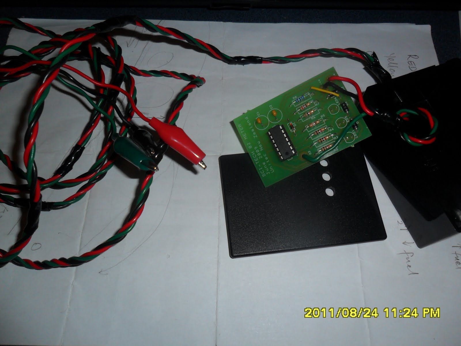

This is my real circuit, now it works very well. But before when I test it, it got a problem. When I connect power supply and change the signal power supply between 0-1volt the yellow LED bright, when the green LED or red LED turn on or turn off so I use multimeter to check available voltage of the yellow LED circuit, and when I checked D3 and I couldn't get reading from component side but I can get reading from soldering side, than I told to tutor he said this called "dry welding" is mean we can see the welding is very well but the pin doesn't connect to the solder, so it doesn't connect the circuit.
Real circuit test on engine
From these to videos we can see when we switch on an engine and use this circuit to test Oxygen sensor and use multimeter to check the sensor's available voltage we can know how does Oxygen sensor works and when the Oxygen sensor change condition it told to the ECU, than the ECU will be supply more oxygen or more fuel into engine make this balance.
No comments:
Post a Comment